Todd Hanneken, June 2025
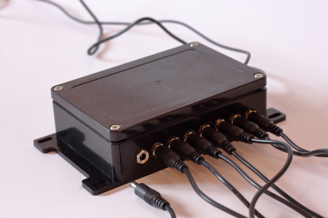
The Octopus lights take their name from the physical structure of the lights with one controller head and eight ports extending to eight light feet. The feet are modular. Any light can be replaced with another light simply by unplugging one light from the head and plugging in a new light. Each light has its own cable, so can be placed anywhere. This is especially useful for raking or RTI illumination. It is possible to connect more than one light to a port if they do not need to be controlled separately. For example, one could connect two LEDs of the same wavelength for greater luminance. It is also possible to connect more than one Octopus to multiply the number of wavelengths, positions, and total amount of light.
The 2023 version of the Octopus was designed to add raking illumination to the MegaVision diffuse narrowband illuminators. Four light feet were placed around the edge of the room with section cups. Each foot was a white 6500K LED with narrow focus optic, producing near-collimated light. The four monochrome raking images were combined with chrominance channels from diffuse processed color to produce color raking images.
More information about the 2023 version is available on its own page.
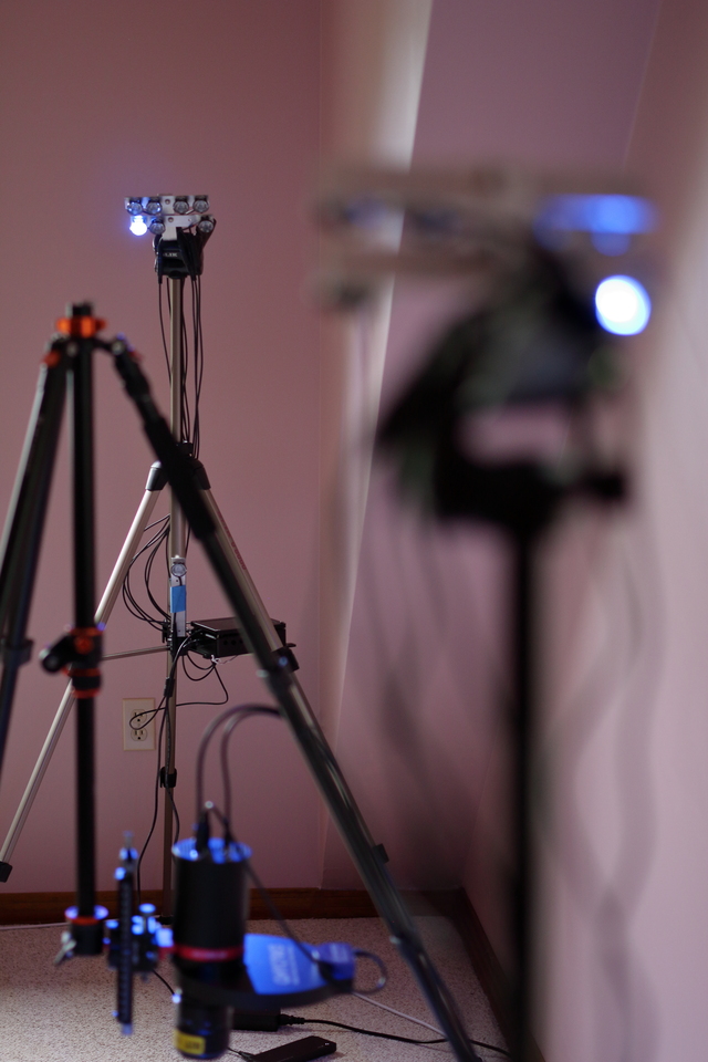
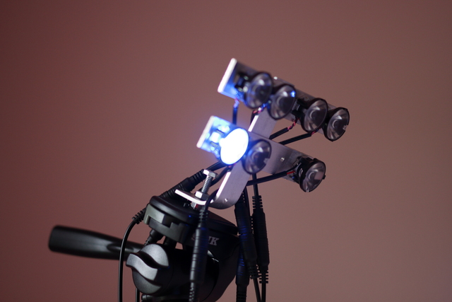
The 2025 version of the Octopus was designed to provide multispectral narrowband and broadband visible in addition to raking. Two heads were built, one for each side of the target to approach diffuse illumination. Each head controlled the following array of light feet:
The sixteen lights (eight on each of two heads) combined with a filter wheel with seven slots:
Images were produced in three categories:
There was no ultraviolet pass filter, so the ultraviolet reflectance images could include fluorescence, but that it not likely to be dominant in the absence of an ultraviolet block filter. The ultraviolet fluorescence images were based on two wavelengths of illumination with three visible pass filters.
The calibrated color images were processed using four illuminators in combination with three visible pass filters, excluding some contradictory combinations. White 6500 Kelvin was captured through blue, green, and red filters. White 2800 Kelvin was captured through blue, green, and red filters. Blue 475 nanometers was captured through blue and green filters. Ultraviolet 405 nanometers was captured through a blue filter. Blue 475 nanometers was used because the light-filter combination had a dip at that wavelength. Ultraviolet 405 is at the edge of the visible, but combined with a blue pass filter gave useful color information. Nine captured images were processed into three channels calibrated to the human visual system using the matrix multiplication method (Amiri et al. 2024). The idea that different kinds of visible illuminators could combine with filters to provide more complete data than white 6500 kelvin through three filters alone had been previously published by (Burns, @@@ find reference).
Infrared reflectance was captured from two illuminators with no filter. It is conceivable that combining the two infrared illuminators with the two infrared pass filters would provide additional information.
Fluorescence in the infrared was captured from long exposures of the white 6500 Kelvin illuminator through the two infrared pass filters.
Four raking images were collected from the two low positions (one from each head) and the two 45° positions (one at a time from each head).
Because the Octopus is built on the principle of modularity, many useful configurations can be imagined. A third head could provide a third angle of illumination, improving diffusion and the total amount of light. A fourth head could increase the number of wavelengths. More filters could also be added, up to the capacity of the wheel available. The QHY mini has an eight-slot wheel. The QHY CFW3 Large has a seven-slot wheel. A port could also power a transmissive light sheet, up to twelve volts of current as controlled by the head (1 amp in the 2023 implementation, 0.5 amps in the 2025 implementation).
So far, all feet used with the Octopus have been based on LED star boards with thermally conducting adhesive stickers to aluminum bars for heat dissipation. The bars can be connected to a wall with suction cups, a tripod with 1/4-20 nuts and bolts, or anything else one might imagine. Feet are connected to the head with M/F 2.1mm barrel jack cables, which can be chained in series for greater length. The LEDs use optics to focus the light, which allows the LEDs to be placed at a greater distance for more collimated light.
The head receives instructions from a capture controller and provides regulated current to the eight ports. Three microcontrollers were used to receive and process instructions. In an effort to achieve compatibility with MegaVision lights and software, the 2023 version use a Microchip microprocessor. For improved availability and community support, the 2025 version used an Arduino controller. There was also an experiment to control the heads over Bluetooth rather than USB. The Raspberry Pi Pico 2W was successful in communicating over Bluetooth. It was also successful in switching at least two MOSFETs, although the 3.3v logic did not work with MOSFETs chosen for the 5v logic of other microcontrollers. The experiment failed when all eight ports were in use. The current best guess as to why is that MOSFETs also function as capacitors. It might be necessary to add resistors to each MOSFET to slow the current when the microcontroller turns on and drain the charge when it turns off. Meanwhile, the Arduino microcontrollers work fine over USB.
LEDs require a regulated current. If a LED driver is not used, the LED will draw more and more current as it heats up until it burns out. The 2023 version used eight drivers, each controlled internally by the 5v logic of the microcontroller. The 2025 version used one driver, while eight MOSFETs were used to control which ports received current. LED drivers are available to control current to 1 amp, 0.5 amps, and 0.3 amps. The choice of driver should be made with consideration of the specifications of the LEDs to be used. Many LEDs specify different values for maximum current and tested-at current. Because there is no limit to the number of heads in use by a capture controller, it would be an option to have different heads with different regulated current.
The pluralization of octopus is a fun topic. Overall, it should be acknowledged that the English plural of the English word “octopus” is “octopuses.” That is the standard rule in English for pluralization of words that end in S. The fact that the English word has a Greek etymology does not determine the declination of the English word. If one wishes to say the word in Greek, even in an English sentence, then one has to decide which Greek pronunciation to use. Octópodes is more widely considered correct Greek pronunciation than octopódes. Both are fun to say, especially if one is in on the joke of being a bit pretentious about one’s knowledge of Greek. The plural “octopi” is based on the analogy with Latin nouns that keep their Latin plural in English.